electronics

Octagon Volume Control

Continuing on a previous post , I managed to do some more work into this.

Basically, the process of cutting off the knob on the octagon port from the inside turned out to be quite difficult.

The small diamond cutting wheels I had was not optimal for aluminium, in fact, they does give a small, clean cut, but the edge also becomes smooth after just a few minutes, making nothing else but heat after that. It took me a while to realize this.

I could also not use the normal dremel cutting attachments, as they were too weak and broke off immediately when applying a bit of pressure.

So, off to the hardware store, and pick up some of my old, trusty cutting wheels with the speed click, the wheels I used (and ran out of) when cutting up the domes last summer. These are 1.5″ in diameter, or 38mm, for all countries in the world except three…

The problem was, that in order to get the cutting disk inside the hole, I needed to make it smaller somehow. And quite a lot smaller, too.

IMG_2579.JPG

I first tried and used the cutting wheel on one of my files. Unfortunately, I forgot I had an old file laying about. It created a nice rain of sparkles, and a groove in my file, but nothing really on the cutting wheel.

Anyway, I found that by running it against one of the diamond-laced cutting wheels (that had useless edges) grinded the cutting wheel down very quickly, to the point where I could actually fit it inside the knob.

After a lot less time than I had already spent trying to detach these, this is what I was left with:

IMG_2571.JPG

The old volume knob was glued in place with E-6000 inside the knob, and it was time to desolder the volume potentiometer from the amplifier.

I added pins to the holes where the amplifier was to be able to attach a cable.easy attaching/detaching.

IMG_2573.JPG

I also built a breakoutboard for the volume pot itself, with a row of pins for the same cable.

IMG_2574.JPG

So far so good. Next step was to build a holder for the pot to reside behind the octagon port. I have decided to add a matte black background to the port (still to be added), but I used a piece of thin, perforated aluminium board in the mean time.

IMG_2575.JPG

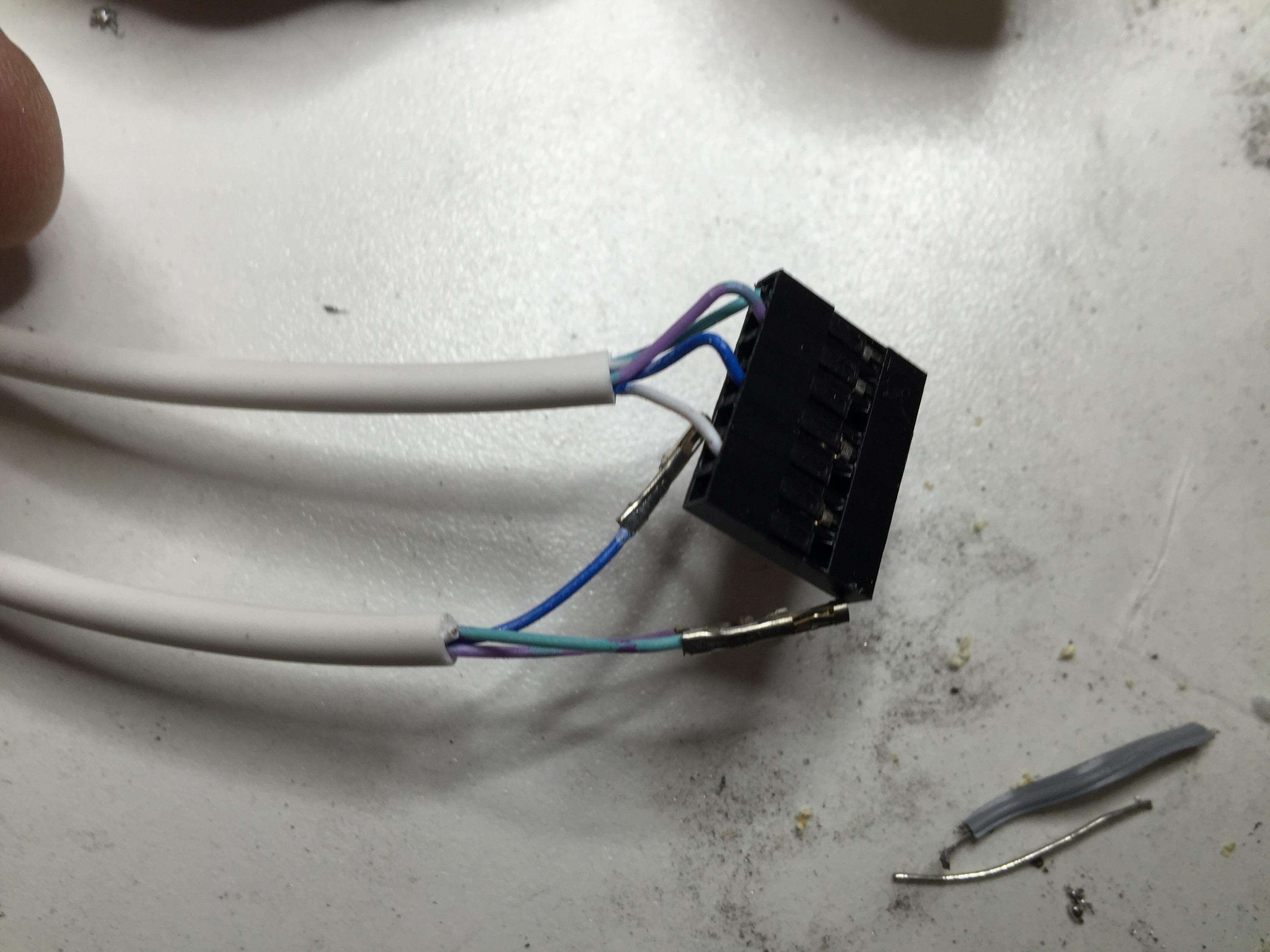
Making the cable was fiddly, since I didn’t have a multi-cable with more than 4 leads, so I had to use two of them.

When assembled, this is the end result:

IMG_2580.JPG

The volume pot rotates without issues, and I’ve tried switching the amp on, and nothing exploded..

All in all, a good upgrade. One of those things that cannot be seen, but the less I need to be reaching inside the droid to do anything in public, the better!

Now, I can easily fix the volume in case he needs to be quiet when there’s a talk going on, or crank up the volume for the parades!

By |2016-12-06T00:00:25+01:00March 21st, 2015|R2-D2|Comments Off on Octagon Volume Control

New Dome Logics installed

As the avid reader might have noticed, a while ago, I decided to upgrade my logic displays in the droid from just standard LED’s to using fiber optics, something that was also used in the original droids.

I ran into an issue when I was almost all done, and part of the plastic bezel that held it all in place broke.

A new bezel was ordered, arrived quickly, and I then set out to reroute 96 new small fibre optic cables.

Here’s a video of what it looked like before upgrading. The LED’s blink and a little too fast, and it is really only white and blue LED’s going on and off.

The original droid used fibre optics connected to a colour wheel, so it more morphed in between white and blue. This is what it looks like now:

Much better, I think.

What’s your opinion?

By |2016-12-06T00:00:25+01:00March 21st, 2015|R2-D2|Comments Off on New Dome Logics installed

Upgrades and fixes..

A little while ago, I listed a number of things that was on my “to-do” list on R2 for this year.

After starting to get some order in my workshop (if only brief), I started fixing up some of the things that I wasn’t totally happy with before.

Things done on my list so far:

  • I’ve drawn and partially printed new ankle cylinders and cylinder holdes and wedges.
  • I’ve painted half my new LDP (ran out of paint. Have bought new paint since then)
  • I’ve painted half of the Ankle Details (Forgot it was two on each foot when I started painting… silly me)
  • I’ve mounted the new Fiber Optics in the dome. Actually broke the rear logics, ordered replacement, assembled that and mounted that as well.
  • I’ve soldered up the rear PSI, which has been an old version for a long long time now.
  • I removed my faulty “Magic Panel” and discovered one of the circuits giving off smoke. Sent it away for possible repairs.
  • I’ve removed the panels from my octagon ports, and started disassembling my main speaker for volume knob relocation
  • Various electronic parts I’ve ordered have arrived. These include: Relay boards, new slip rings (larger and smaller), extra amplifier and speakers.

Next task would be to mount the newly soldered PSI in the dome, cut away the disc part of my octagon port panels and glue (or 3dprint and glue) the volume knob in place. I also need to desolder the volume potentiometer and build a break-out board for it, and mount on the back on the octagon panel.

I have also received a new raspberry pi with a camera module, and will work on mounting that in the dome. Probably with addition of movement and distance detection as well.

The list of things to do is still as long as my arm (and then some), but making progress little by little. The big thing I want to fix is really the ankle, and fixing the broken down motor for the new foot drive I made.

Anyway, enough ranting, here are some pics! =)

IMG_2522.JPG

R2 looks strange without the panel from the octagon port.. Both of them gone..

IMG_2519.JPG

This is the one.. Removed and up close you can really tell how crude my job was at weathering my droid..

IMG_2520.JPG

The back side. I will be cutting away the cut-out from the inside. There’s a “lip” going all around which is not visible. This is where my cut will be, allowing the “knob” to rotate and function as volume control for R2! Not that it matters, but I’ve marked which way is up and which is the front and back for clarity..

IMG_2523.JPG

This is the behemoth rig I’ll use to cut it all out. My trusty dremel with my router addon. It will actually be the first time I use this addon!

IMG_2525.JPG

A diamond cutting disk… I am planning on using alcogel hand cleanser for cooling when cutting through the aluminium.

IMG_2526.JPG

I will be cutting from the inside, this is just to double check that my cutting wheel is at the correct distance. This should give me a cut fairly in the middle of the “lip” that you can see on the knob to the left.

IMG_2527.JPG

The actual cut will be blind, as I cannot see the cutting wheel, and it will be hard holding on to the knob, but I’ll certainly do my best. Again, one of these things that would be a lot easier if I actually had a proper work shop for this.

IMG_2528.JPG

Volume know from the amplifier removed. It will be mounted inside the hollow part (which will be cut off..) It will sort of look a bit like …

IMG_2529.JPG

…. this.

IMG_2517.JPG

Here is the volume potentiometer inside my amp. I will need to de-solder it, and build a small breakout board for it in order to have the volume in the octagon knob.

IMG_2518.JPG

Only 7 solder points, (one being an optional ground, but I kind of want to be on the safe side here…) Should be easy once I relocate my solder sucker and braid…

IMG_2531.JPG

The rear PSI, all soldered and done! Would have been ready ages ago unless I had run out of LED’s.

IMG_2530.JPG

Hopefully, all LED’s are soldered in a checkerboard pattern…

IMG_2532.JPG

This one was actually finished years ago…

IMG_2533.JPG

.. and was mounted inside the droid temporarily, with duct tape.. I am not 100% sure how i will mount it, but that is also on my todo list..

By |2016-12-06T00:00:27+01:00March 15th, 2015|R2-D2|Comments Off on Upgrades and fixes..
Go to Top