Ghostbusters

Ghostbusters Project: Building a Booster

One of the few items I have left on my pack is the booster tube.
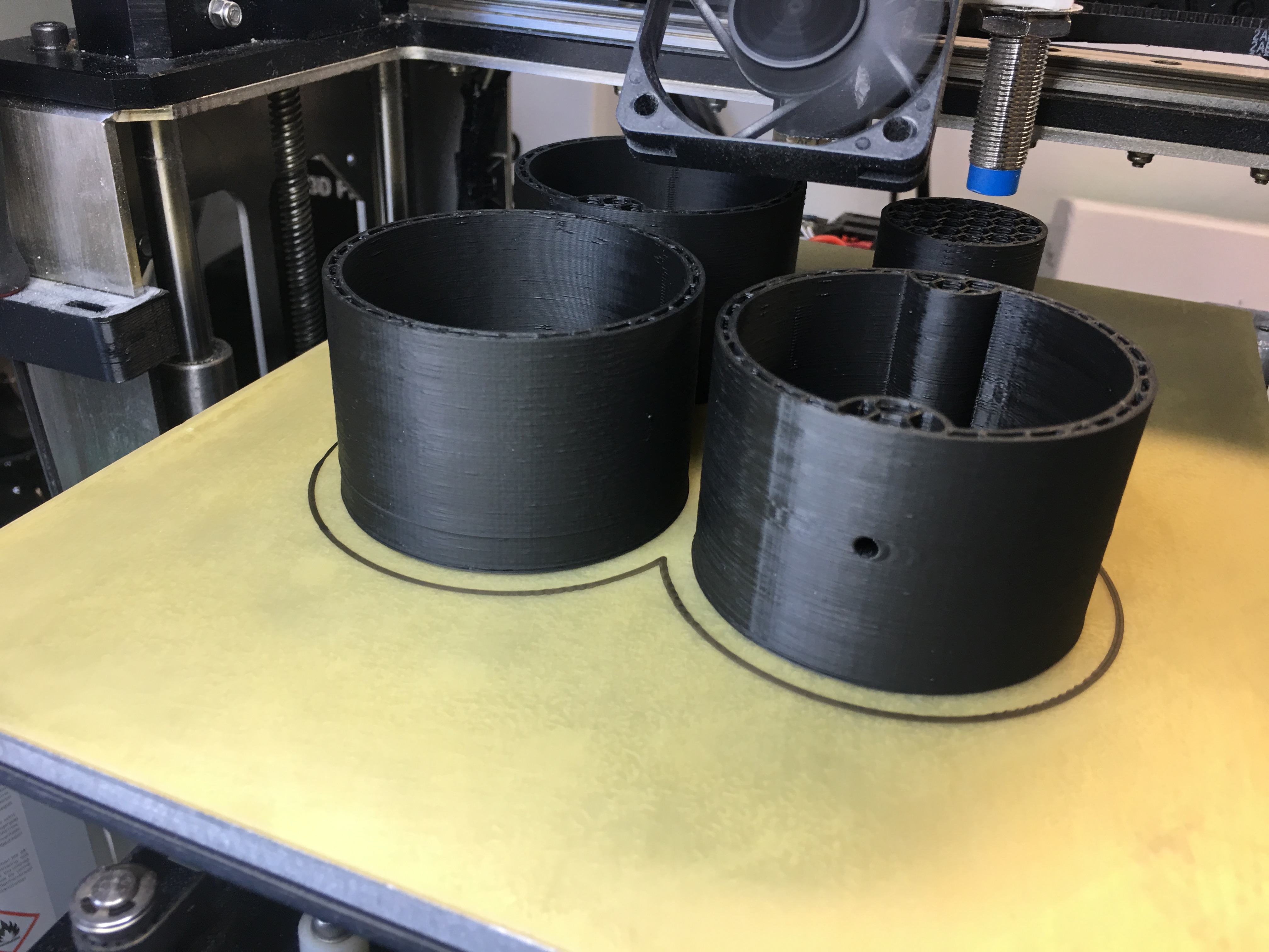
I sourced a few nearby stores for fitting tubes in PVC, but found none that were even near the proper diameter, so I decided to make my own. Let’s get that 3D printer to work!

Now, the print went over night and when I started it last night, I was tired and used the wrong settings, so it is all spotty and blobby, but the new one above is straight off the printer with no sanding using the correct settings!.

Here are all the parts:

The booster plug just fits inside the outermost part of the booster tube, and is fastened from the inside with an m3 bolt.

All parts of the tube are designed to be screwed together to help when gluing them. I use these brass inserts that I just head press into the plastic and i just love them!

They are simply pressed into the plastic with my soldering iron, so they are melted in place.

All three parts fit together, and all holes are already made into the design.

Apart from the annoying spots, this looks pretty ok!

Here is the new booster tube, printing as I write this, and will keep on printing for another 10 hours or so. It looks much better when printed with the correct settings!

Finally a few shots of the pack with all now painted and fastened parts, apart from the booster tube and frame, which are the last parts to be mounted on the pack.

By |2017-06-08T23:23:56+02:00June 8th, 2017|Building, Ghostbusters, Ghostbusters Proton Pack|Comments Off on Ghostbusters Project: Building a Booster

Ghostbusters Project: Assembling the Pack vol. 1

My original plan was to build a true “hero” pack, with all the parts from the original that was made out of metal in … well.. metal.

However, things change, and what changed in this case was time. Time to finish the build, time to make this one complete, before I am forced to put it aside for many many months…

The thing is this: I need to take my family abroad to treat my daughter at a specialist clinic in a country I’ve never been in, and which language I do not speak.

Since it is quite far, all my hobby and building projects will need to be put on hold within the next 2 weeks or so, so I am trying to finish up as much as I can on this pack before it’s put into storage for the next 8-12 months.

I will not delve further into what is going on with my daughter, but if you WANT to know, feel free to visit www.goEmma.se. Be warned. It is not a fun read.

However: I decided that it was time to use the resin parts I had laying about and start putting the pack together!

One of the first things I assembled was the Ion arm:

This was the easy part, but as the ion arm made from resin is hollow, and basically has no base plate, I had no idea how to mount it yet, as I want to be able to one day replace the resin parts with metal, as the original plane was. While I was thinking about it, I started drilling and fastening and putting some other parts together.

Next up, the HGA:

I then simply drilled and fastened the beam line, and filler tubes, the injector tubes and the vacuum tube. All these were done by printing out the mount plate I designed for the metal parts to paper, tape one copy to the resin part to get the hole configuration, and one copy to the pack to drill the holes where they should be!

Measure twice and drill once… At least that’s what I should have done. When I started adding things like the bumper, I realised after a while that it was a bit crooked.

Not a big issue, I plugged the hole with some epoxy putty and measured (the second time), correct this time, and drilled a new hole.

For the bracket that holds the injector tubes, I used this:

I cut it down to size, and used a file to round off the edges…

Then simply put a large clamp on it, and used my body weight to bend it to 90 degrees against a piece of wood. Then drill holes and screw it in to place in both the injector tubes and the shell. I decided to use screws since I want to be able to replace these at some point…

To fasten the HGA, I taped a piece of paper around the round, open edge, and used a scalpel to cut around the inside edge to get the inner circumference, and cut a scrap piece of 3mm styrene I had laying about to the same size. I then pressed some epoxy putty around the inner edge of the tube and pressed the styrene circle inside and let it sit until the epoxy had hardened. Once cured, I simply used the paper pattern from my virtual HGA in order to get the holes where I wanted them to be. I then tapped the holes and everything was done!

The Ion arm I tried something different. Since I only really needed to make holes near the corners, I built up the inside of the hollow ion arm with two-component epoxy putty. Same stuff I used on the HGA. Once it was almost cured, I sanded off the chunks and carefully drilled some pilot holes.

Once fully cured, I tapped these as well and I drilled the corresponding holes in the shell.

Last step for tonight, was to drill and tap the holes for the cable clamp. Naturally I had to add the cable just for fun. I also drilled the hole in the shell where the cable will end up, eventually. The cable needs to be quite a bit shorter, but as I haven’t made my booster tube yet, I won’t cut it just yet.

I am fast reaching the end of the things that can be done on the outside of the pack, apart from painting the resin parts. I’ve got a few more holes to drill and places for cables to run, and making that booster tube, but other than that, things start to look pretty good.

I do however still have a lot to do on the thrower, where I plan to 3d print panels for the inside of the thrower, to hold the electronics and rumble pack in place, and use the existing bolts from the outside to mount these panels. Hopefully, it will work!

One thing I have started on designing, is a holder for the reflectors for the cyclotron that are pushed against the lenses with springs, in order to have them as close as possible.

The reasoning behind this, is that I really don’t want anything at all connected to the shell, so I can simply lift it off and have everything sitting on the motherboard.

I’ve printed out a few smaller pieces to test sizes, but I have yet to print out a POC, but I am aiming for something like this to hold my reflectors…

More to come soon…

By |2017-06-05T23:52:30+02:00June 5th, 2017|3D Printing, Building, Costuming, Ghostbusters, Ghostbusters Proton Pack|Comments Off on Ghostbusters Project: Assembling the Pack vol. 1

Ghostbusters Project: Mounting the pack

Since I received my motherboard, I could start working on attaching the motherboard to the frame, and the shell to the motherboard.

One of the first things I simply had to try, was to fit the speakers on to my laser cut grille, and they matched up perfectly!

Next up was drilling the holes into the Alice Frame, which was a lot harder than I thought, but it worked out fine.

Once the motherboard was attached, I started attaching the L-brackets that holds the shell to the motherboard.

I used very strong magnets to hold them in place while I gently pushed then around with the shell to get where I wanted them, then drilled through and riveted from the back, as per the original packs. When they had been placed, I taped them while I carefully marked the positions for them with a sharpie.

Note that I let the L-bracket underneath the mount point for the thrower lie down, in order to make proper space inside for the metal reinforcements I will put inside.

Of course, not all of them were a perfect match, as I don’t have a proper work bench or drill press. One of them moved around a bit, but with a little filing, it fit just fine.

With the pack clamped down on top of the brackets, I drilled through the shell (going backwards first) with a 3mm drill, then continued in into the L bracket to get the hole at the precise correct place.

Once the guiding hole was done, I drilled upp to 5mm on the brackets..

.. before I hand tapped them to 1/8″.

Tapping is hard work, and with aluminium, it is important to lubricate (I used isopropanol) and go forward a turn, then back half a turn, lubricate, and repeat.

Just look at these lovely blue Pyle speakers. They will make my pack loud!

Once all holes were tapped, I screwed the motherboard in to place..

And had my (bored) fiancée take the obligatory first pictures of me wearing my work in progress:

Let me know what you think. I think it fits well, and looks like it has a good height on me.

One thing that bothers me though, is I think my shell is a bit wonky, turns out that there is a gap…

With a little mild pressure, it closes nicely, however. I’m not sure how to solve this. I think there might be a place on my shell that needs a bit of filing, but I might also make some bracket that this can hook in to from the inside. We’ll see.

I am not too worried, though.

Finally, as a closer, I also received these:

By |2017-05-24T22:41:28+02:00May 24th, 2017|Building, Ghostbusters, Ghostbusters Proton Pack|Comments Off on Ghostbusters Project: Mounting the pack
Go to Top