construction

Modified Electronics and New Coin Returns

Hello!

After a break where I’ve focused on other, more important things in life for a few days, I got around to do some more building today!

It felt good actually doing something again. Building is like therapy!

First off, I was given a few aluminum … thingies .. that works extremely well to divert heat from my motor controllers!

I purchased some thermal grease and took apart the motor controllers, added a healthy amount of grease, then added more grease to the aluminum surrounds, and finally screwed these to my new heat sinks!
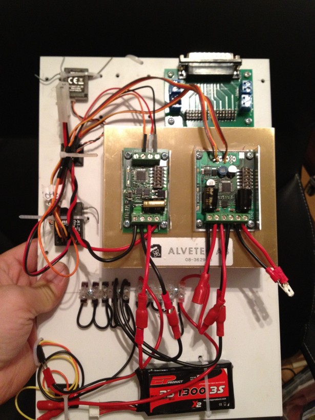
My first version was to screw these on the insides, in order to have more space for cool air to cool these down, but I quickly realized that I would not be able to see the status LED’s on my motor controllers!

These will do fine, and allow plenty of air to pass through.
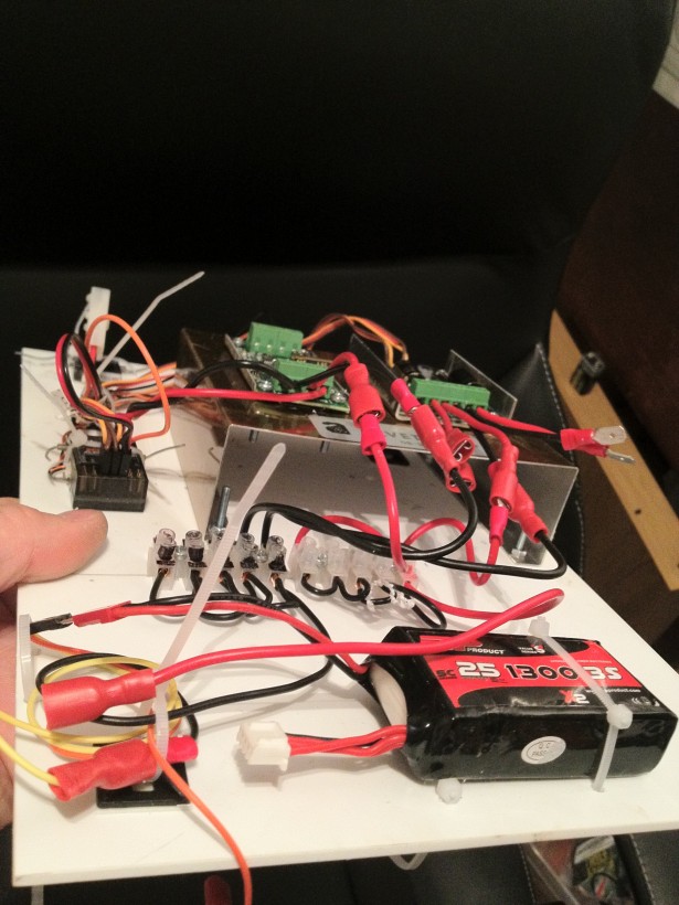
This should make the motors to not overheat so easily… hopefully!

A few days ago, I picked up a 0.8 mm thick aluminum plate, and decided to try and do something with my coin returns and vents. I had made one coin return before, and the idea was simply to exchange the from plate, which was styrene with aluminum tape, with proper aluminum.

I started marking out the pieces and started cutting them out. I used the same idea as for styrene. I scored with a sharp break-blade knife and a steel ruler, and this enabled me to bend the aluminum back and forth until it snapped and gave me a very clean edge.
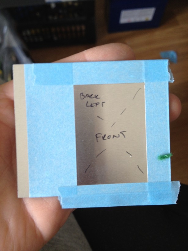
I scored the edges where I needed to cut out, and also masked this off with tape, to (try) to keep the aluminum surface nice and clean. At this state, I drilled holes in the corners and I bent the plates using a scrap piece from the frame as guide, and checked with the placement on the droid.
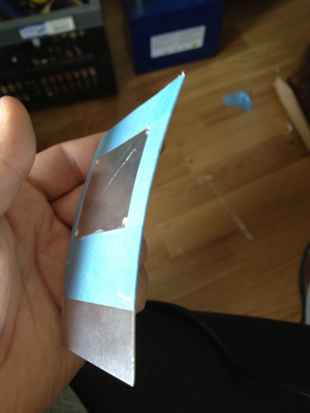
Thin aluminum was not that hard to work with, and I decided to actually try and make the entire coin return out of aluminum. I printed out some templates, glued it on the aluminum and started cutting.
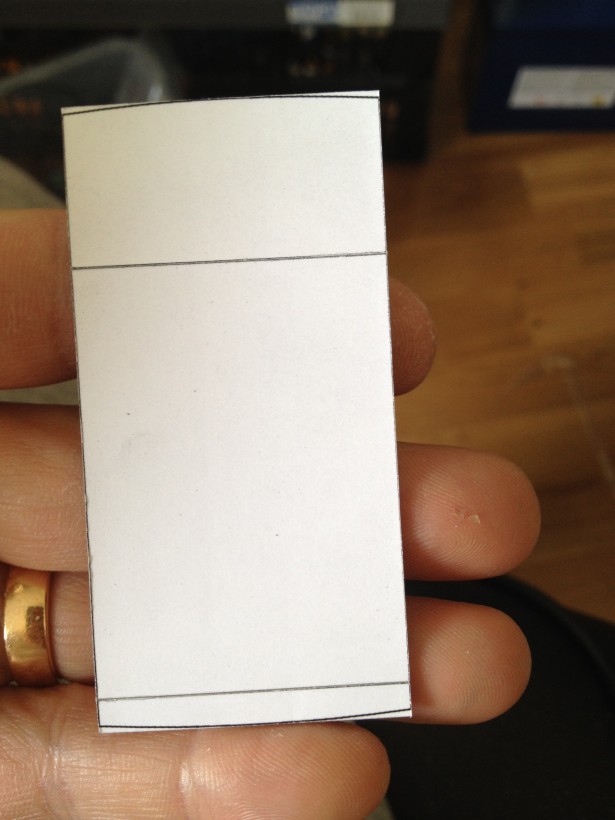
I used the knife to score the edges where I wanted to bend the aluminum.

The rounded parts, I sanded off with my dremel.
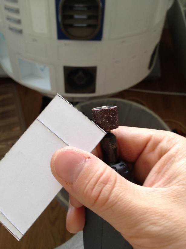
Since the aluminum was scored, bending it was rather simple, but I knew I would only have one chance on bending it. If I needed to bend it back and forth, it would snap. Since this is a small detail, it does not bother me that the coin returns are scored on the back, as it is facing inside the droid, and no one will ever see it.
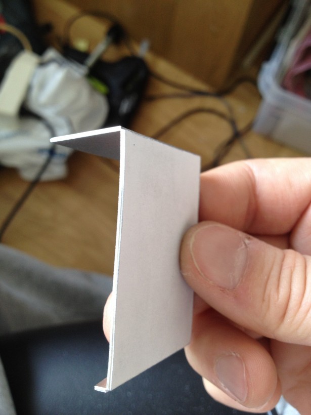
As you can see, the aluminum is clearly weakened where it is bent, but I plan on filling this with putty anyway, and it is not a piece that will be in any stress anyway.
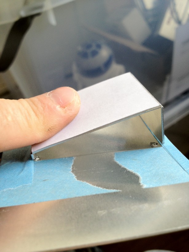
Testing on the rounded piece… Yep, fits good!
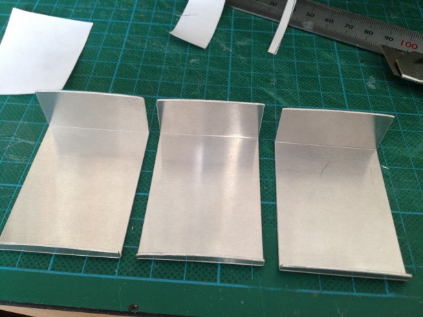
All three coin return innards done. One for the front and two for the back!

The sides will simply be made slightly too large and glued on.
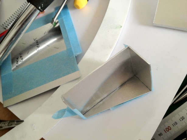
Once the sides are in place, time to glue the entire innards on the front plate and superglue them together.. and then add platy of tamaiya putty in order to really fix them together.
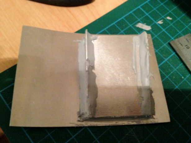
… now I know what you’re thinking….
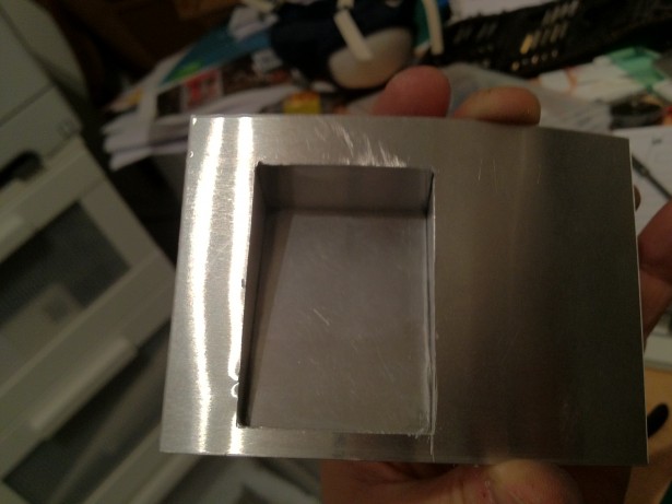
I did not forget to actually cut out the square from the front plate!

This is the front coin return, all in aluminum. Check out how good it looks on the test fit on the body:
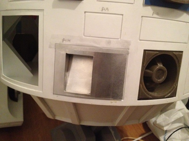
Sure, it has a few minor things that are not perfect, but this is R2 we’re talking about. He should be a bit dented up and not pristine clear. I will do some more sanding and filing later on, but I think it looks good on him =)

Finally, I had to do a comparison shot in-between my old styrene coin return and the new all aluminum one:
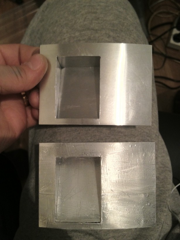
A small detail, really, and I have a lot more to fix this week, so why did I focus on redoing something I’ve already done?

Well, why not? =)

I needed to start to learn how to work with the aluminum parts I need to make anyway…

//Micke

By |2016-12-06T00:01:36+01:00March 26th, 2012|R2-D2|Comments Off on Modified Electronics and New Coin Returns

Second foot shell..

One of the first things I did in my R2 build was one of the foot shells. It was with that I learned how to work with styrene, and also what not to do.

That is one reason why I decided to build one foot shell at the time, and the second foot shell has eluded me for almost the entire build.

Now, no longer.

I started the build on the second foot shell a few days ago, and so far, it has gone quite well!

Yes, a can of spray glue and a bottle of greek olive oil was used to skin the foot shell, to get the proper curved face. Last time, I simply did this freehand, and using these can made my life a LOT easier!

It did however cause a new, interesting problem. In order of fasten the printouts on my other styrene pieces, I had to improvise, as I had taped the can of spray glue to my foot shell already..

Here below are the detail pieces of the bottom of the foot shell.


Assembled and ready. Now on to the final pieces for the detail plate of the foot shell.

As the faithful reader you are, you may remember that I’ve already finished the half-moons a while back…

This means that it was a simple task of cutting the detail plate and the parts that goes on it –A fairly simple job!

Glued and ready…

Nice and clean when ready! =)

Next step is to glue the detail frame and plate onto the otherwise ready foot shell…

Looks pretty ok, even the curved piece looks pretty decent!

Last thing done for the day was to remove the tape and fill in the joints with Tamaiya Putty. This is done, and the foot shell is setting until tomorrow when it is time to sand most of it off, and get nice and clean seams!

Once this is sanded, only big construction thing left, is to finish off the second battery box, which in reality only means skinning it, and that’s done fairly quickly!

Then time to work on the dome for the next week and a half to get the dome presentable for the sci-fi convention in two weeks!


By |2016-12-06T00:01:38+01:00March 18th, 2012|R2-D2|Comments Off on Second foot shell..

Boxing Day!

After more bloodshed, I’ve continued my work on the battery boxes.

Firstly, I skinned the first one:

It took a little while, as I had to do it in stages. Once the styrene was wrapped around and fixed, I could cut open the openings and finalize the Battery Box:

Here’s the battery box screwed in to the main foot shell and also the motor holder. It will hold the foot shell and the box in place. The battery box will not contain any batteries, but merely serve as an extension for the motor to extend into, and also for the cables to have a bit of slack.

Note the large rim around the opening…

I dressed the lid of the battery box in 1mm styrene, and made the lid slightly larger, in order to get the box opening as smooth as possible.

Closing in the cables… The hole is tapped for M3 at the moment, and I think I will superglue a nut on the back of the inside holder in order for this to have better longevity, as styrene and M3-M4 tapping really exhausts itself quite easily.

Still needs a little bondo and sanding, but it closes pretty tight

Naturally, the screws will be countersunk as well, but I had no M3 screws with the right head for it at home!

Here’s a full view on the mounted battery box…

… and another one.

As you can see, the ribs inside the box are visible on the outside. Sanding + bondo will take that right out, and that’s a project for then it’s time to prep the box for painting!

I’ve also adjusted the position of the screws into the legs, as I realized that the legs were a tad shorter than the official measurements. They had simply slid too far into the ankle, and I placed a few styrene shims on the bottom of the ankle to fix this.

This means the legs are even! =)

As I cannot make the second battery box ready until I have the second foot shell, well .. there’s only one thing to do!

Get down to business!

While making this second foot shell, I’ve tried to avoid the mistakes I made on the first ones. So far, so good. I’ve made a whole new set of mistakes again!

Fortunately, I’ll be the only one who can spot them!

I’ve constructed this foot shell after the same model as the first one, but in a slightly different order, and it seems a lot more stable this time around.

I’ve also sealed up all seams in the foot shell with Tamaiya Putty, for stability. I’ve used a full tube of putty for this foot shell alone!

Here’s a half messy pic of the putty applied to the seams inside the foot.

Tomorrow is the job of adding the bottom details on the foot, and skin the sides. With any lucy, this foot is complete before the weekend!

However, I did spend a few hours on the dome as well.

Drilling, dremeling (and almost burning out my dremel copy, gotta get myself a proper one), sawing, bending and filing. First hole for the HP is done. It took a while!

At this moment, I cannot really say that I’m looking forward to cutting up the pie panels, the other two HP holes, the two PSI holes and the three Logic Displays.

Aluminum is a whole new material to work with, and a whole new array of mistakes to be made.

More blood has been shed…

//Micke

By |2016-12-06T00:01:40+01:00March 14th, 2012|R2-D2|Comments Off on Boxing Day!
Go to Top