upgrade

Almost faceplant, repairs and small upgrades…

I took R2 out a little while ago, since there was a huge Star Wars fan at work who was leaving the company, and I decided to bring R2 and make his day.

On the way there, my small cart that I pulled R2 on, came to a full stop, and R2 plummeted forward.. was I finally going to have the dreaded face plant? On a gravelly city street none the less? *gasp*

Fortunately my lightning fast reaction managed to save the droid before the front hit the mix of gravel and tarmac, but not without battle damage. The tiny door around the charging bay panel took a hit. The hinge was bent, and the door was broken off in two places. I was lucky I found all three parts of the hatch to begin with!

I got through the day (and a subsequent official Disney / LFL event) by adding a bit of scotch tape… first to hold the panel together, second to hold it in place.

R2white

Yesterday was the day to start fixing that, and also to make some time for some small upgrades!

First off, I managed to get the hatch lose from the hinge inside. The hinge was bent beyond repair, as it is totally impossible to remove the hinge and correct it. It is one of those things that needs to be done before it is installed. I had glued the hinge to the inside of the robot using E-6000 glue, which turned out to be holding the hinge insanely hard. In spite of trying to cut it lose, bend it lose or pry it lose, it only resulted in me breaking the hinge even more. I took a sturdy pair of pliers and broke off all parts from the hinge sticking out, leaving only the “flat” part that was still glued to the inside of the skin. I would have to work with this and glue the new hinge on top of the old one…

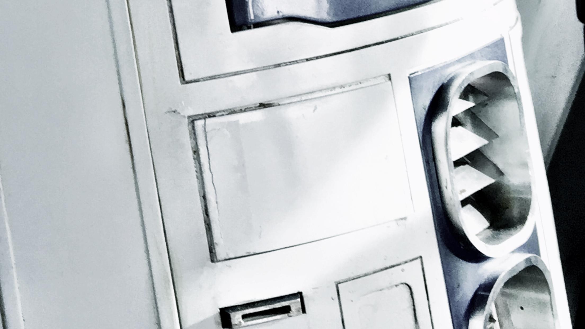
So, for starters, there’s a gaping hole in the front of my droid. New hinge is not yet mounted.

IMG_3829.JPG

At least I’ve got a straight, working hinge..

The hatch has been glued together with superglue.

IMG_3831.JPG

Technically, I could build a new one, but the painting is a bit of a hassle when you live in an apartment, and getting the weathering to match might be even more so. Besides, the visible cracks can still be extra weathering and battle damage. I have even considered adding a darker wash to the crack to make it even more visible.

Next step: I took my front speakers and changed the way they were sitting in my amp. They wer just clipped in my amp, and one of the clips had broken lose, so I soldered the cables inside my already modified and soldered amplifier (see Octagon Volume Control) and added a proper, sturdy connector to be able to remove it easily:

IMG_3834.JPG

I have also prepped a second amplifier, that is supposed to drive two speakers that will be sitting right inside my side vents.

So, since I was in doing things, I pried lose the back plates from my old side vents… and let some air in.

IMG_3825.JPG

Next step: cut out and lightly bend new back plates out of perforated aluminium

IMG_3826.JPG

In place, they are still see through…

IMG_3819.JPG

But, with an added layer of black felt behind it, it should be invisible. I still need to add a bit of weathering to the back plate though.

IMG_3821.JPG

At the moment, the idea is to mount speakers from within on metal brackets, and possible cover the white frame parts in black felt, and surround the speaker with black felt as well, creating a totally black trap behind the vent. It will create a little bit of depth, but also not showing anything of the frame behind the perforated plate. The plate needs to be perforated in order to let the sound waves through properly, of course.

These speakers

IMG_3822.JPG

will be mounted on two brackets like this

IMG_3823.JPG

on the inside. The brackets were made from aluminium and I broke off two of them before I realized that heating up the aluminium with my blowtorch REALLY helps when you need to bend it! =)

I also soldered the cables in place needed for the new amp and pulled out a power cord for it. Done. I still need to route out the second volume knob like I did on the first droid, but I will require a little help with that this time.

I also took out my Rogue Robotics mp3 shield, which is really old and have no updated libraries for my arduino since 2012, and resoldered the 3,5 mm socket back in place, it had broken lose somewhere. It works now, but it sounds like there is no volume coming from it. Fortunately, it is no problem for my amplifier!

A bit of updating and tweaking the sound code in my arduinos (The new panel with the USB connectors is SO great! Best idea ever!)

IMG_3828.JPG

… and it is working a lot better. STill lots of things to mount and tweak.

Next step will be to program my new XBee and replace the old one in the transmitter. Not because it is faulty, but rather because of the huge antenna. It’s not like I need 300m+ range on my droid after all. The much smaller one has a more limited range, 100 meters in open terrain, but as long as I have a range of 10 meters, I’m more than fine. I never like to be away from my droid anyway …

IMG_3833.JPG

That’s it for now… more shortly!

By |2016-12-06T00:00:20+01:00May 12th, 2015|R2-D2|Comments Off on Almost faceplant, repairs and small upgrades…

More Data Panel..

Will this never end?

MORE on this data panel nonsense?
Yes! Indeed!

First the easy bit: I removed the 3d printed coupling once again, and superglued it in place, instead of the hot glue that was not doing its job.. but that was not the big thing!

Basically, I had done the bulk of the panel, but lacked the surrounds for it. I started by looking at the surrounds I already had on the A&A Kit I purchased some years ago and realized that’s not going to work.

So, using that as a template, I started cutting and filing and doing my thing in some 1mm styrene to come up with something like … this:

IMG_3002.JPG

I painted that with Satin White, and drybrushed it with some old, trusty “Mithril Silver” and glued it in place..

IMG_3005.JPG

filthied it down, just like I did the original panel.. (Using “Chaos Black” and “Flesh Wash”. Really putting these two old Citadel colours to work here)

IMG_3006.JPG

.. before I went over it with cotton pads and a solvent to clean it up and also burn the weathering into the lacquer paint.

IMG_3007.JPG

It really looks the part (pun intended) now, and it feels more solid.

I tested it in place, and it is ready to be fitted in place, but before I go down that route, there were a couple of other things needs to be done first.

First off, since I want this hatch to be openable, and I didn’t prepare anything for it, I realized I needed to route a hole in my top ring around the utility arm area:

IMG_3026.JPG

I fastened an M4 screw in place and it sticks up just enough in my routered path that it works!

IMG_3031.JPG

While doing this, I also removed the old magnet holding the door shut… and shimmied off some material that was catching when the door was closing… and this is when R2 realized that “hey, it’s been too long since a blood sacrifice was made”..

IMG_3028.JPG

Once the bloodlust of R2 (Bet you didn’t know he had one. All builders can agree with me that he has one) was settled, I could finish off the short time of work for the evening, which was to switch two cables on the dome motor, to make R2 turn his head in the direction I want him to!

Next up is attaching a servo to the frame, and start working on getting this hatch to close… not sure how that’s going to go, to be honest….

When working in cramped areas like this I really wish I had a set of old dentist tools and drills.. it could make live SO much easier 😉

By |2016-12-06T00:00:21+01:00April 12th, 2015|R2-D2|Comments Off on More Data Panel..

Data Panel!

So, A long long time ago in a galaxy far, far away.. I had temporarily mounted one of the inside panels of R2 with duct tape.

The circuitboard was assembled, held in place behind the panel by duct tape, the panel was unpainted, looked flat, and .. you guess it .. held in place by duct tape.

Not to mention the arduino running the program for the blinky lights…

Anyway: I figured that if I wanted this panel to be in my droid, I had to do something proper with it. I have not had it inside my R2 for a long time, and I had an idea what to do with it:

From this:

IMG_8256

To something like this:

DataPanelUSB

I have 4 arduinos in the body of my R2-D2, and easy access to them is something that I have long sought after…

First step was to start cutting up the panel..

IMG_2886.JPG

A while ago, I ordered a bunch of USB cables for panel mounting. I just needed to cut away some portruding things on the insides, and then I simply taped four of them together.

IMG_2887.JPG

Test fit behind the panel..

IMG_2889.JPG

It fits perfect!

However, I wanted to have something more, not just a long gaping hole with 4 USB’s, so I made a sort of bezel from 1mm styrene.

IMG_2901.JPG

A test fit, to see if it works, and how it looks..

IMG_2903.JPG

Just testing to see that the USB plug reaches in deep enough to sit properly. It does.

Next step was to drill up the holes where the connector should be properly, take the panel and bezel outside and paint the panel. Satin White, of course. The bezel, I decided to paint in R2 Blue. I needed to try something out.

I also designed and 3d printed a few distances for the circuitboard to go around the round LED’s at the bottom and to the right. Everything was hot glued in place and works like a charm.

For the LED’s up right, I cut up a piece of 1mm acrylics, drilled and riveted in place. The edges cracked when I did the riveting, but as I’m planning on weathering the panel, it really makes no difference.

IMG_2926.JPG

Time to weather the panel! I used the same method I used for the rest of my droid, but made this one to be a little more cleaner, as it is on the inside of the droid. I filthied it down with the remains of my old Citadel Paints: Chaos Black and Flesh Wash. Once really soiled, I used cotton pads and a solvent to clean off just enough to make it look clean..ish.

I also took some sanding paper and dulled down the clear acrylic, and banged on the acrylic with the handle of a screwdriver until it cracked a little more. It looks just the part.

IMG_2948.JPG

Something is still missing. The connector. It is just a slight engraving and some holes on this panel. I decided it needed something else. The research I’ve made suggests that it is a multi cable connector, and I drew one in Rhino3D and printed on my Makergear M2.

IMG_2949.JPG

Once done, I gave it a quick acetone vapor bath…

IMG_2947.JPG

… and finally hot glued it to the panel.

IMG_2950.JPG

MUCH better!

I still need to do a bit of work on the body of the droid to mount this in place, but I was so happy that I had to do a quick pic with the panel in place:

IMG_2951.JPG

Finally, a short youtube clip to show off what it looks like in action!

The inside of the panel is the next step with this part. I need to add ridges to mount the panel against, and also weather the inside of the hatch. That, however is work for another day! 😀

By |2016-12-06T00:00:22+01:00April 5th, 2015|R2-D2|Comments Off on Data Panel!
Go to Top