r2controller

Disaster, Recocery and moving along…

Last week, I took R2 out to a gaming/cosplay convention in Uppsala, Birdie Expo!

Birdie is also one of very gracious sponsors of the VERY nice R2 Builders backdrop we (now) have!

IMG_3892.JPG

Anyway, day 1 went by well, I managed to get some time in hooking up a servo, rerouting some cables (the quick and dirty version) and doing some code on both my receiver and the new arduino I placed inside R2.

Since I was doing most of this on the fly, with a lot less tools that I usually use, the result was… well .. let’s call it “less than optimal”.

Sure, I got R2 working GREAT with both the new code and the new panel and some of the extra tidbits in it (still not finished with the code, but that will be done at a later time), but .. the results are quite horrible.

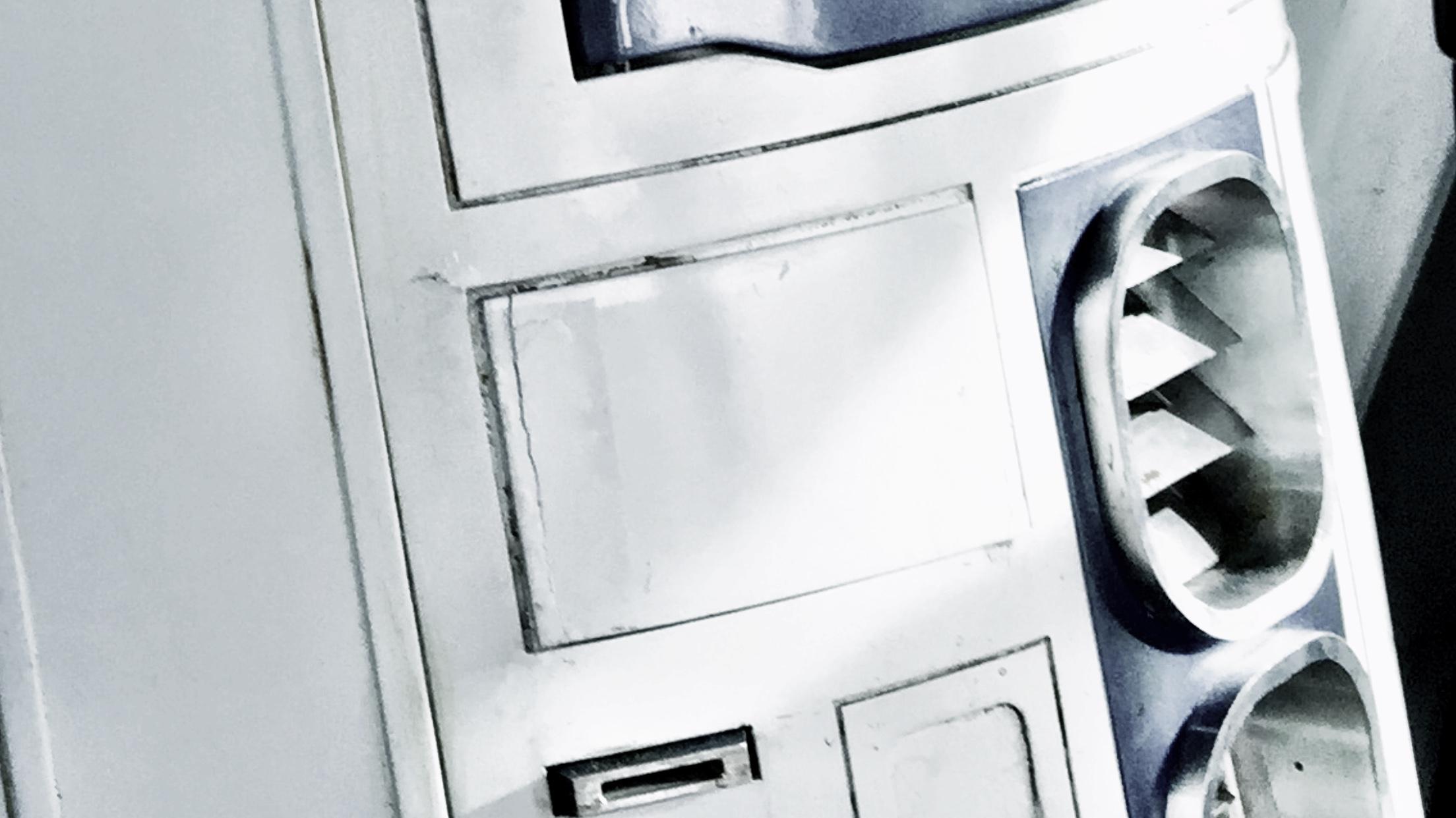
The insides of my R2 body now look like this!

IMG_3884.JPG

The extra amp, speakers, arduino and servo, without any properly done cabling at all, has turned my once so tidy R2 inside to a gigantic web!

So what was the results? .. well … this!

So, end user result is great, and I’m really happy. It is also the FIRST motorized servo in R2 I’ve done code for, so it marked a milestone!

For well over a year, I’ve had servos in the dome hooked up with no place to go. Now, this will change..

Second day of the Expo started out great.

I thought I’d get some time doing some tweaks in the control board when times were slow, but after a quick update, something went terribly, TERRIBLY wrong!

R2 started jerking, moving by himself and seemed really weird!

A little debugging told me that the communication between the bluetooth wireless Wii Nunchuck I was using, and my controller board had gone bananas. Instead of receiving real world values, it started receiving random signals.

Turns out that the old libraries used (third party) had not been upgraded in the past 3.5 years, and the later versions of arduino seemed to rupture something. (I did try and reinstall an old version to no avail).

So, I had to sit down and focus and see if I could fix the issue.

It ended up with me programming an arduino library for the nunchuck myself from scratch. I had no idea how or what to do when starting out.

About two hours later, R2 is back and moving again! PHEW!

Good thing though, is that now I can throw out the buggy code, and maybe even get more third party nunchucks working with better resolution!

Back at home after the ordeal, I’ve spent a few evenings looking in to the updated controller code, and will soon move over to the whole new branch of code I’ve written and improved upon from the original R-Series code to various contributions form other people.

Not wanting to sit and just do coding, I decided to get the hooked up servos in the dome moving.

I decided to not use the small Adafruit breakout board for 16 servos that I had, mostly because I cannot detach the servos at will, like I can with normal Arduino coding.

Said and done, I found a Servo shield at a local hobby place, bought it, took it home, only to realize that it was the shield version of the same Adafruit PWM board.

Now, that board could work great, if only I knew how to detach a servo in it, and unfortunately I don’t.

Instead, I purchased an empty shield and did some soldering. An hour or so later it was time to make the cables for it (which is a really fidgety job that takes way longer than people think, cutting, peeling, crimping, removing bad crimps, peeling, crimping again, realize it is not sitting tight, remove the second bad crimp and make a third one… and so on.

Once that was in the head, I started hooking things up and got really weird results from the first servo. First servo alone. It wasn’t supposed to be doing anything… yet.

I removed all code that would make any servo move, and still I got really weird results from a servo. Why? what’s going on?

I pulled everything out again and started writing from scratch… turns out that after a bit of googling on what I found, pins 0 and 1 on the Arduino are earmarked for Serial connection, so you have to disable the serial in order for them to work as a normal pin….

Once I found that out, I managed to get a sketch going, and started setting max and min values on the servos.

Not having a lot of time, I did not have time to investigate why one of the servos are not moving. The pie panel not moving in the video is not moving since the nut and bolt that was holding the piano wire that connects to the servo, fell out. Something to fix later on when I investigate why my servo on the 3rd panel doesn’t work.

Here’s a quick video I took after setting the max and min values. I’m not done yet by a long shot, but at least it is a start!

That’s all for now!

more updates next week!

By |2016-12-06T00:00:18+01:00May 19th, 2015|R2-D2|Comments Off on Disaster, Recocery and moving along…

Almost faceplant, repairs and small upgrades…

I took R2 out a little while ago, since there was a huge Star Wars fan at work who was leaving the company, and I decided to bring R2 and make his day.

On the way there, my small cart that I pulled R2 on, came to a full stop, and R2 plummeted forward.. was I finally going to have the dreaded face plant? On a gravelly city street none the less? *gasp*

Fortunately my lightning fast reaction managed to save the droid before the front hit the mix of gravel and tarmac, but not without battle damage. The tiny door around the charging bay panel took a hit. The hinge was bent, and the door was broken off in two places. I was lucky I found all three parts of the hatch to begin with!

I got through the day (and a subsequent official Disney / LFL event) by adding a bit of scotch tape… first to hold the panel together, second to hold it in place.

R2white

Yesterday was the day to start fixing that, and also to make some time for some small upgrades!

First off, I managed to get the hatch lose from the hinge inside. The hinge was bent beyond repair, as it is totally impossible to remove the hinge and correct it. It is one of those things that needs to be done before it is installed. I had glued the hinge to the inside of the robot using E-6000 glue, which turned out to be holding the hinge insanely hard. In spite of trying to cut it lose, bend it lose or pry it lose, it only resulted in me breaking the hinge even more. I took a sturdy pair of pliers and broke off all parts from the hinge sticking out, leaving only the “flat” part that was still glued to the inside of the skin. I would have to work with this and glue the new hinge on top of the old one…

So, for starters, there’s a gaping hole in the front of my droid. New hinge is not yet mounted.

IMG_3829.JPG

At least I’ve got a straight, working hinge..

The hatch has been glued together with superglue.

IMG_3831.JPG

Technically, I could build a new one, but the painting is a bit of a hassle when you live in an apartment, and getting the weathering to match might be even more so. Besides, the visible cracks can still be extra weathering and battle damage. I have even considered adding a darker wash to the crack to make it even more visible.

Next step: I took my front speakers and changed the way they were sitting in my amp. They wer just clipped in my amp, and one of the clips had broken lose, so I soldered the cables inside my already modified and soldered amplifier (see Octagon Volume Control) and added a proper, sturdy connector to be able to remove it easily:

IMG_3834.JPG

I have also prepped a second amplifier, that is supposed to drive two speakers that will be sitting right inside my side vents.

So, since I was in doing things, I pried lose the back plates from my old side vents… and let some air in.

IMG_3825.JPG

Next step: cut out and lightly bend new back plates out of perforated aluminium

IMG_3826.JPG

In place, they are still see through…

IMG_3819.JPG

But, with an added layer of black felt behind it, it should be invisible. I still need to add a bit of weathering to the back plate though.

IMG_3821.JPG

At the moment, the idea is to mount speakers from within on metal brackets, and possible cover the white frame parts in black felt, and surround the speaker with black felt as well, creating a totally black trap behind the vent. It will create a little bit of depth, but also not showing anything of the frame behind the perforated plate. The plate needs to be perforated in order to let the sound waves through properly, of course.

These speakers

IMG_3822.JPG

will be mounted on two brackets like this

IMG_3823.JPG

on the inside. The brackets were made from aluminium and I broke off two of them before I realized that heating up the aluminium with my blowtorch REALLY helps when you need to bend it! =)

I also soldered the cables in place needed for the new amp and pulled out a power cord for it. Done. I still need to route out the second volume knob like I did on the first droid, but I will require a little help with that this time.

I also took out my Rogue Robotics mp3 shield, which is really old and have no updated libraries for my arduino since 2012, and resoldered the 3,5 mm socket back in place, it had broken lose somewhere. It works now, but it sounds like there is no volume coming from it. Fortunately, it is no problem for my amplifier!

A bit of updating and tweaking the sound code in my arduinos (The new panel with the USB connectors is SO great! Best idea ever!)

IMG_3828.JPG

… and it is working a lot better. STill lots of things to mount and tweak.

Next step will be to program my new XBee and replace the old one in the transmitter. Not because it is faulty, but rather because of the huge antenna. It’s not like I need 300m+ range on my droid after all. The much smaller one has a more limited range, 100 meters in open terrain, but as long as I have a range of 10 meters, I’m more than fine. I never like to be away from my droid anyway …

IMG_3833.JPG

That’s it for now… more shortly!

By |2016-12-06T00:00:20+01:00May 12th, 2015|R2-D2|Comments Off on Almost faceplant, repairs and small upgrades…

R2 electronics upgrade

Hello! =)

I will update about the big event in Stockholm, and also about the charity event I did with R2 on Christmas Eve shortly.

In brief: R2 and the 501st collected a lot of money to battle children’s cancer in early December, and on Christmas Eve, I took R2 with me to visit poor children in Stockholm to give them a happier Christmas.

I managed to get a few 501st friends and a magician with me to help out with this. Kudos to them!

Anyway, back to what this update is about!

After the Sci Fi convention, I decided to work on my new controller again, and it has gone great!

This is my old electronics board. Well. Was.

IMG_7629

I removed all components and started installing components on the new board..

IMG_7630

Three layers worth of circuit boards, 3 Arduino computers.. and more to come!

IMG_7635

Complete with two motor controllers, one sip ring connector board..

IMG_7637

Many of the cables are run on the backside in order to keep the front as clear as possible.

All ground connectors are run through the aluminium plate, by the way.

IMG_7639


This is the arm controller that I’ve been working on. I will change it some more, but for now, this is what I can do.

I will draw a better version in my CAD software and send it to Shapeways to print for me in plastic! That will be sweet!

This is still a “beta” but it is really getting a lot better!

IMG_7640

Plenty of boars inside. The curved piece was made from styrene with a blowtorch.

IMG_7643

It sits great on the arm…

IMG_7642

And it even works!

Since this beta, I’ve replaced the touch screen, which had a crack through it, and been working hard on the code for the controller.

This is what the controller touch screen looked like before I started:

IMG_7737


A fairly easy way with text. Nothing fancy.

However, it turned out to be quite hard to actually touch those lines, as they are really thin, and my fingers are .. well .. not.

So, after spending a good couple of hours with my head into the code, this is what I’ve made it to look like instead:

IMG_7732


And when moving to another page..

IMG_7734


… and when you select an item, this is what it does now:

IMG_7736


In addition to that, I’ve done many tweaks when it comes to things like speed, motor controllers, dome control, and the sound effects for the dome.

When I started with this controller, I was not happy with the level of control I had over my robot, but after tweaking the code and changing things around, it really starts coming together in a way that I am really happy with!

Next step is to design the proper arm holder and draw it up in my CAD software!

Stay tuned! =)


By |2016-12-06T00:00:38+01:00January 6th, 2013|R2-D2|Comments Off on R2 electronics upgrade
Go to Top