construction

Ankle Work

Since the dawn of time… well.. since R2 was finished originally, that is, he’s had a pair of heavy resin bulks under the Ankle Cylinders.

The Ankle Cylinders was scratch built 3 years ago, and was basically a piece of PVC pipe with thin strips of styrene wrapped around it, with custom made end caps.

See this post for the original build: Scratch building ankle cylinders! They have done the trick up until now, but I wanted to have a set that looked a bit better.

The main reason for revisiting this, is that the original pieces have only been taped to the ankle with double stick tape that has (mostly) done the job, but they have had a tendency to fall off.

I don’t want to glue things in place here, as if I need to do any work on the cables inside, I need to be able to remove these to get to an access hole that is hiding behind them.

I had also lost a few of the ankle wedges (see Building an ankle wedge) that is supposed to sit on top of the cylinders. They were also just taped to the ankle…

The total assembly looked like this: IMG_6906

(Mounting the Ankle… stuff)

But now it was time to fix everything in this area. I had not been 100% happy with the aluminium tape wrapped around the pipe, even if it has done the job.

So, armed with my trusty CAD program, the avid reader know that I have been printing Ankle Cylinders in the past.

This is the parts that I drew and printed:

IMG_7791

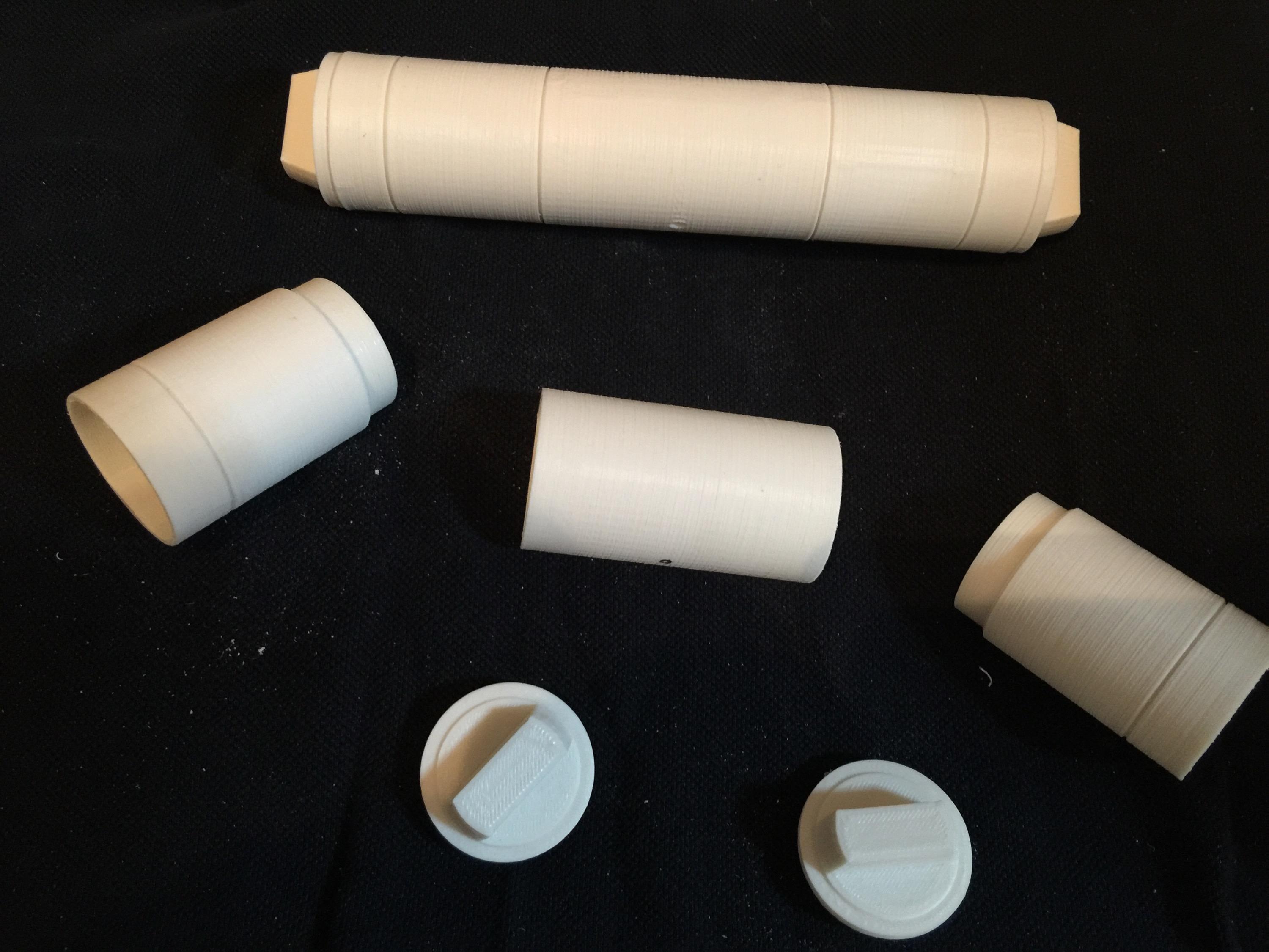
These were printed apart to get the grooves in the cylinder as sharp as possible.

IMG_7790

The new ankle cylinders holders. 3D printed, hollow and extremely light. I have glued 12mm magnets inside them for holding them to the ankle later on.

IMG_7789

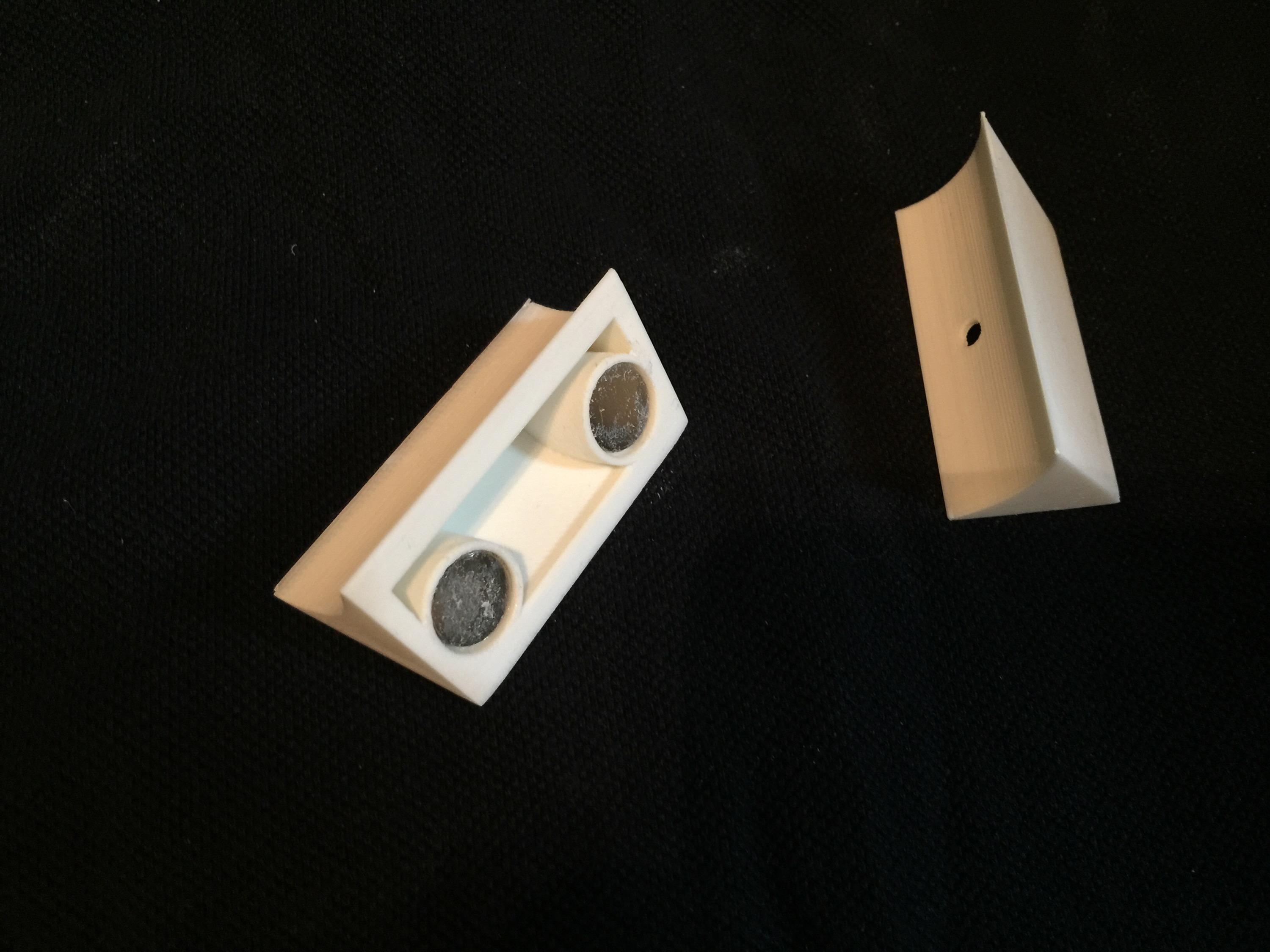
Here are the new wedges. They are a lot sturdier and better than my old ones! These ones also has magnets inside them. The idea is to pin the wedge inbetween them.

IMG_7792

Like this.

Since I can disassemble these, it makes for easy painting.

IMG_7911

End pieces sanded and ready for painting!

IMG_7909 IMG_7910

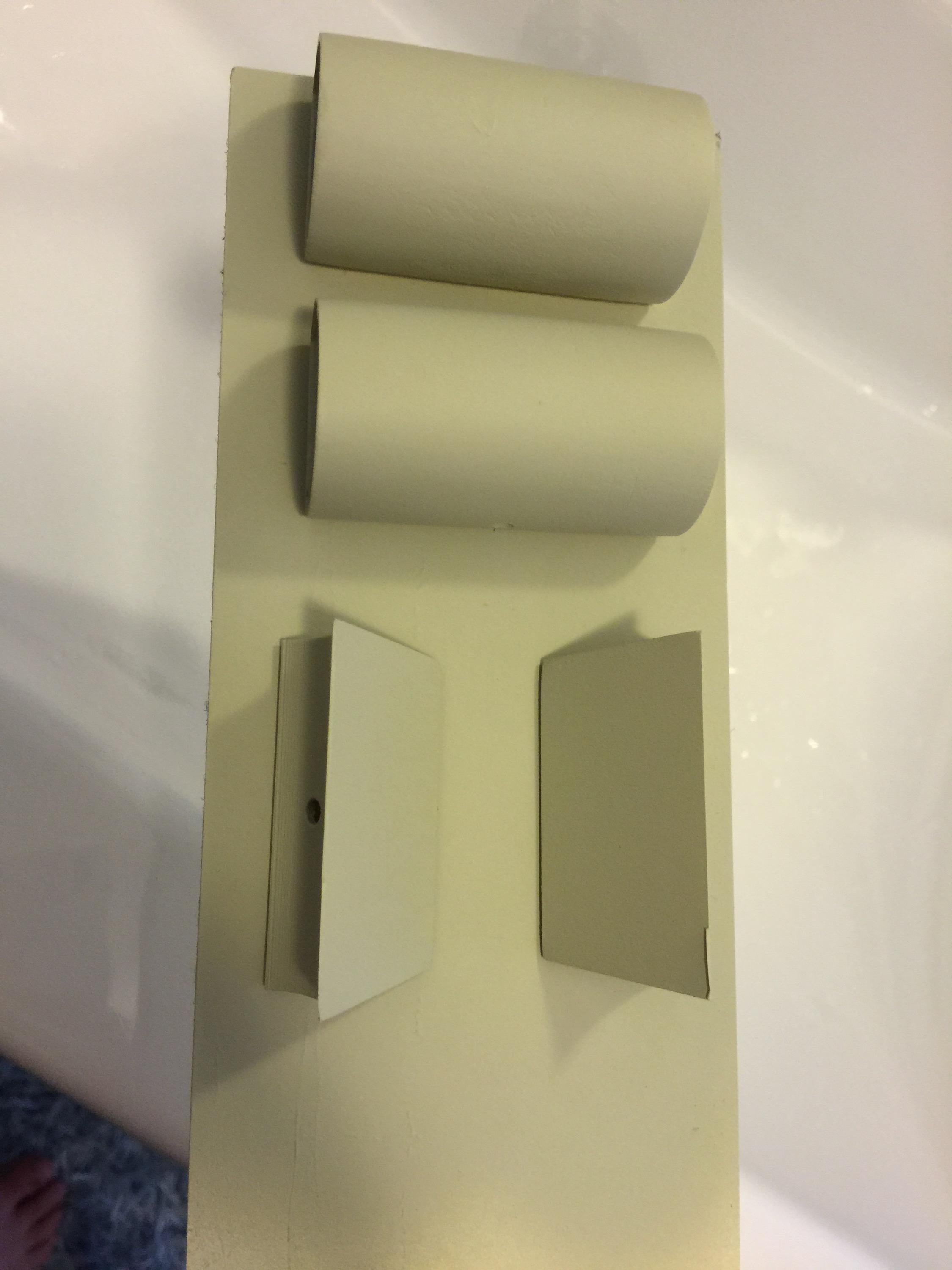
I started off by painting them with a filler primer. I chose this as it fills up any imperfections after not sanding enough, or print imperfections.

A dab of the old “Satin White” ..

IMG_7914

… and some R2 Blue…

IMG_7912


… add a little rub and buff …

IMG_7918

… and the assembly should be ready for mounting on the droid.

IMG_7919


I must say I am very happy with the results. The rub and buff really looks like metal!

Next up, fixing the magnets to the droid..

All in all, a great upgrade. Next up is adding the new Ankle Details in aluminium and then weather the new pieces on the ankle.

Finale assembly:

IMG_7923

By |2016-12-06T00:00:10+01:00August 30th, 2015|Building, R2-D2|Comments Off on Ankle Work

A working Computer Interface Arm…

For a while, I’ve really wanted to make a working “computer interface arm”. I had one made in aluminium a while ago, but this proved to be way too heavy for my styrene droid, so I decided to sell it.

When looking at the movie, R2 “flips up” his arm, then the tip extends, and it rotates as it is inserted into the computer interface.

r2_interface_arm

Image from starwarsscreencaps.com. (c) LucasFilm / Disney.

Most likely, this is accomplished by some sort of magnet lock, and it is actually the wall panel that rotates, and the tip of the interface arm only “tags along”. It is a hundred times easier to make, and this was after all done in 1976, so most likely, That is what happened.

That is not what I’m planning. I’m planning to make a computer interface arm that can both extend AND rotate!

I plan to accomplish this through a simple method:

The thick part of the interface arm is a hollow plastic tube. The tip is 3D printed and mounted on an aluminium tube.

This tube is inserted into a smaller aluminium tube that is fixed within the hollow plastic tube with 3D printed parts.

Inside the aluminium tube, I mount a stiff cable on a holder from a tackle shop, that can rotate as much as it wants.

The stiff cable goes through the assembly to the back end, where a servo can either push out the tip, or retract it. Pretty much the same way an electric car antenna works.

The tube in which the cable resides, has gears glued on to it, and can through a 360 degree servo rotate in either direction. The stiff cable inside, which controls the extension/retraction movement is still in place, and the small tube with the tip attached to it, rotates around it.

Sounds complicated, and to some degree it is: Have a look at these images and see if it makes more sense:

IMG_4681

IMG_4682

These pictures have the rear servo taken out for clarity, and also the inside tube removed for clarity. The inside tube would have slots cut out to make contact with the outer gears.

Now that my 3D printer is upgraded and make better parts than ever, it is time to set this all into action! 😀 Stay tuned!

By |2016-12-06T00:00:13+01:00August 25th, 2015|R2-D2|Comments Off on A working Computer Interface Arm…

Fixing a wobbly leg

Hurrying a build will always come back to bite you later!

When I originally built my R2, I was in a building frenzy. In a way, it was almost therapeutic for me, as I needed to get my mind off things, and really focused as much as I could into the build.

The legs was one of those first things I made, and I did not let the fact that I did not have a drill press stop me!

So, instead of .. I don’t know .. ask any of my friends if any of they had access to one, I basically drilled the holes in my ankles freehand. I know for a fact, that these holes have not been straight.

The symptoms of this, has been that my R2 always drifts towards the left when I drive him, and even though I can compensate, as soon as the drive power stops, and he rolls a few decimeters, he always steers off to the left. This has really been a pet peeve of mine, even though it is something only I was aware of, but isn’t that the definition of a pet peeve anyway, more or less? 😉

So, armed with a plan, I took R2’s legs to my friend Anton’s work (where they have a proper drill press) and got to work.

This is the problem area: (and no it isn’t dirty. It is only painted that way)

IMG_6888

IMG_6889

A few years ago, I did have the foresight to protect the existing ankle holes, so I had drilled the holes slightly larger and inserted a piece of aluminum tube to not let the threaded bolt eat into the plastic. When the foot was removed, I got proof that my ‘protection plan’ had worked as it should: The threads from the bolt had really eaten into the aluminium bolt! Just imagine what could have happened if it had gone straight into the plastic ankle?

IMG_6890


So, the force has been strong enough to not only impress the threads into the aluminium tube, but also to slightly deform the hole!

My plan was to make a new hole, a straight hole this time, and rather than the existing tubes, I would insert some sort of bushings into the hole.

I had these linear ball bearings that will do just fine for the job at hand:

IMG_6891

First step was to affix the leg to the drill press… and slowly drill through both ankle and the existing aluminium tube to straighten up the hole..

IMG_6893


Since the aluminium tube was only fixed with E-6000 inside, it soon pushed out the other end, while the drill made a straight hole through..

My friend Anton did the first one:

IMG_6892


.. and I drilled the second hole. Scary but a VERY quick fix in the end. The new bushings were pushed in to place …

IMG_6894

A much better solution, and a more solid contact area towards the plastic!

I also took the opportunity to attach the new motor holders (as seen in “Fixing a hobbled droid” and “Fixing a hobbled droid, part II”). Yes, even though I had made these new motor holders way back, I had to abandon them due to a motor dying on me, but this has since been fixed, and this seemed like a great opportunity to put them in action!

Since fixing this, I have not yet had time to do a proper event with R2, but I’ve got a two day event in September that will be a perfect test. I will bring along my backup motor holders just in case… you never now.


By |2016-12-06T00:00:14+01:00August 25th, 2015|R2-D2|Comments Off on Fixing a wobbly leg
Go to Top