R2-D2

All things related to R2-D2

Vicker Viscount Reading Light Mount

Some A lot of parts in Star Wars are based off existing parts. Once you start learning what things are, you keep on seeing the shapes and parts everywhere.

IMG_8251

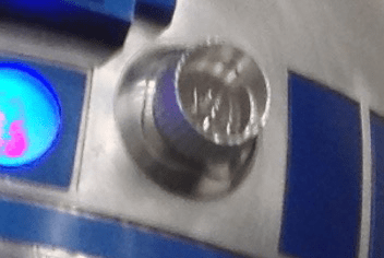
One example, which is used on multiple places, is the series of metal ridges on the right hand side of R2, which can also be found on the chest box of Darth Vader.

Turns out these were the actual coin slot of a British 60’s phone box.

Spare parts from scrapped technology was quite common. A lot of the weapons used in Star Wars was based on second world war remnants, just modified to look better and cooler!

Microphone tips from a particular brand called Hovi have been used in Stormtrooper helmets, Biker Scout helmets, Communicators, and possibly more.

Dashboard from an old Volvo have been used as interiour in the Millennium Falcon, and most notably as control panels on Han Solo frozen in Carbonite.

The Imperial Uniforms had previously been seen in a 60’s Sci-Fi, and the boots used were either post-war East German marching boots, or British riding boots. Why re-invent the wheel?

However, this post is not about those, but about the “Holo Projectors” on R2-D2. The thing that broadcasts the message from Leia in Star Wars: A New Hope. Yes. That one.

IMG_7525

When you look at it, it is quite obvious that this part, is originally the reading light found in older air planes. In this case, from a Vickers Viscount 700-series aircraft.

A while back, my good friend managed to track down a few of these..

Vickers

Ledtråd1

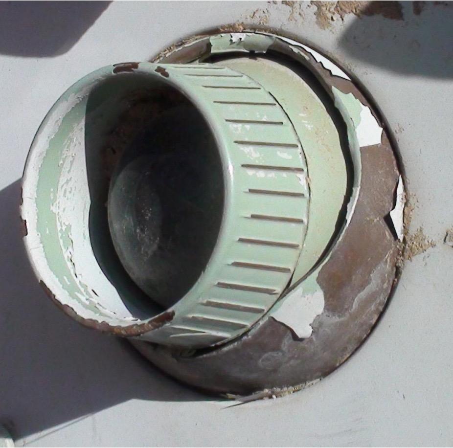
..and sent me this one!

It has been sitting in a box for a long time, only brought out at some Sci Fi conventions and R2 Builder meetings to show other builders, but I felt it was time to get to work on making a proper display for it!

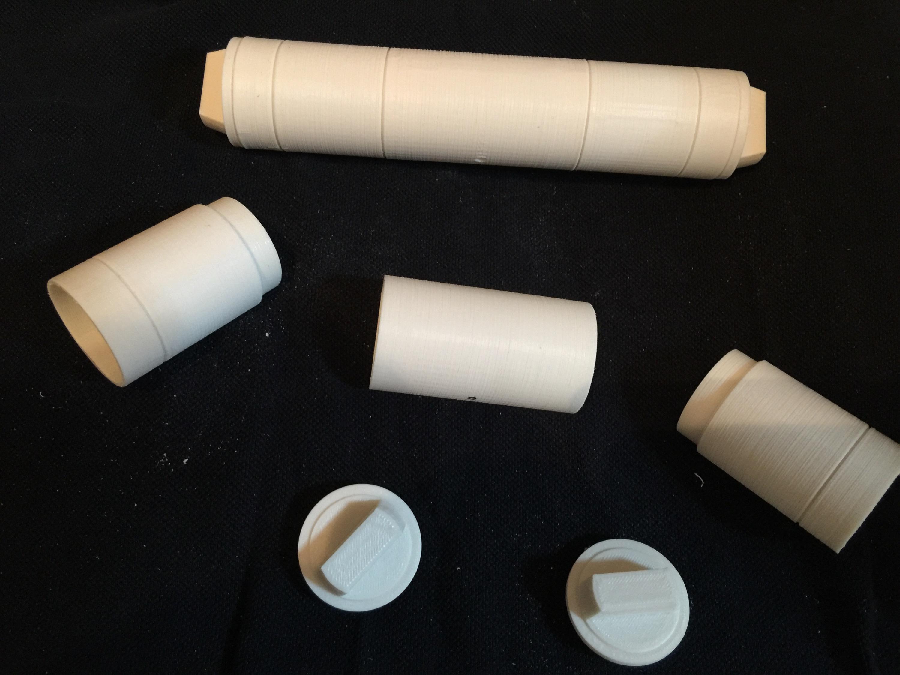
First up was getting all the grime off, which took a while. A lot of sanding to get dirt, sand and oxidation go, and then I started to work on the display bit.

I had a few sheets of clear acrylic laying about, and while the reading light was 65 mm in diameter, I had a hole drill that was just below that, so I figured it would be perfect!

Drilling up the big hole, followed by testing the mounting worked great.

Next up was deciding how I wanted it displayed.

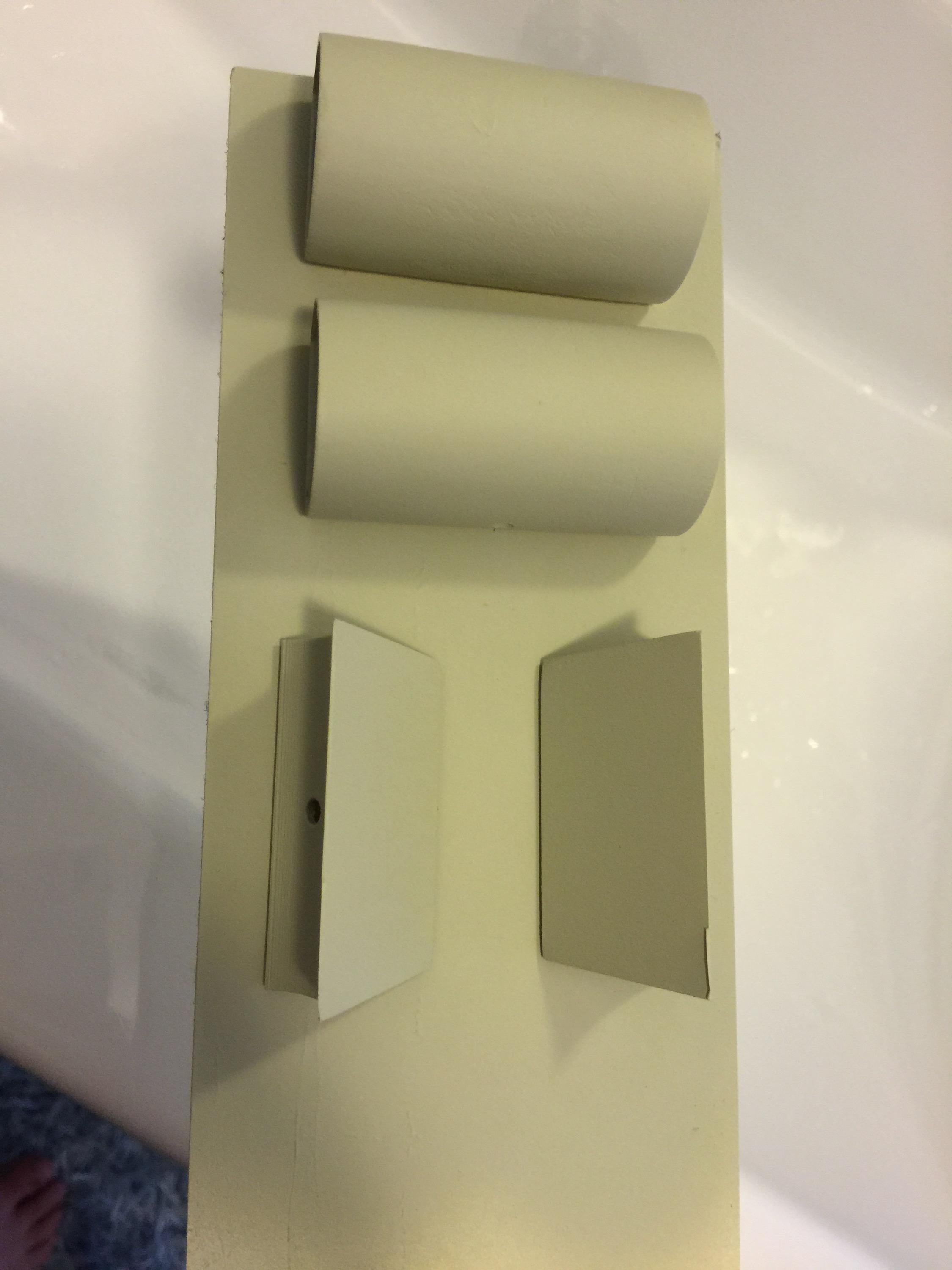
I opted for a smaller display piece, and wanted protective acrylic both in front of and behind the reading light. Time for some cad!

Screenshot 2015-10-02 22.36.30

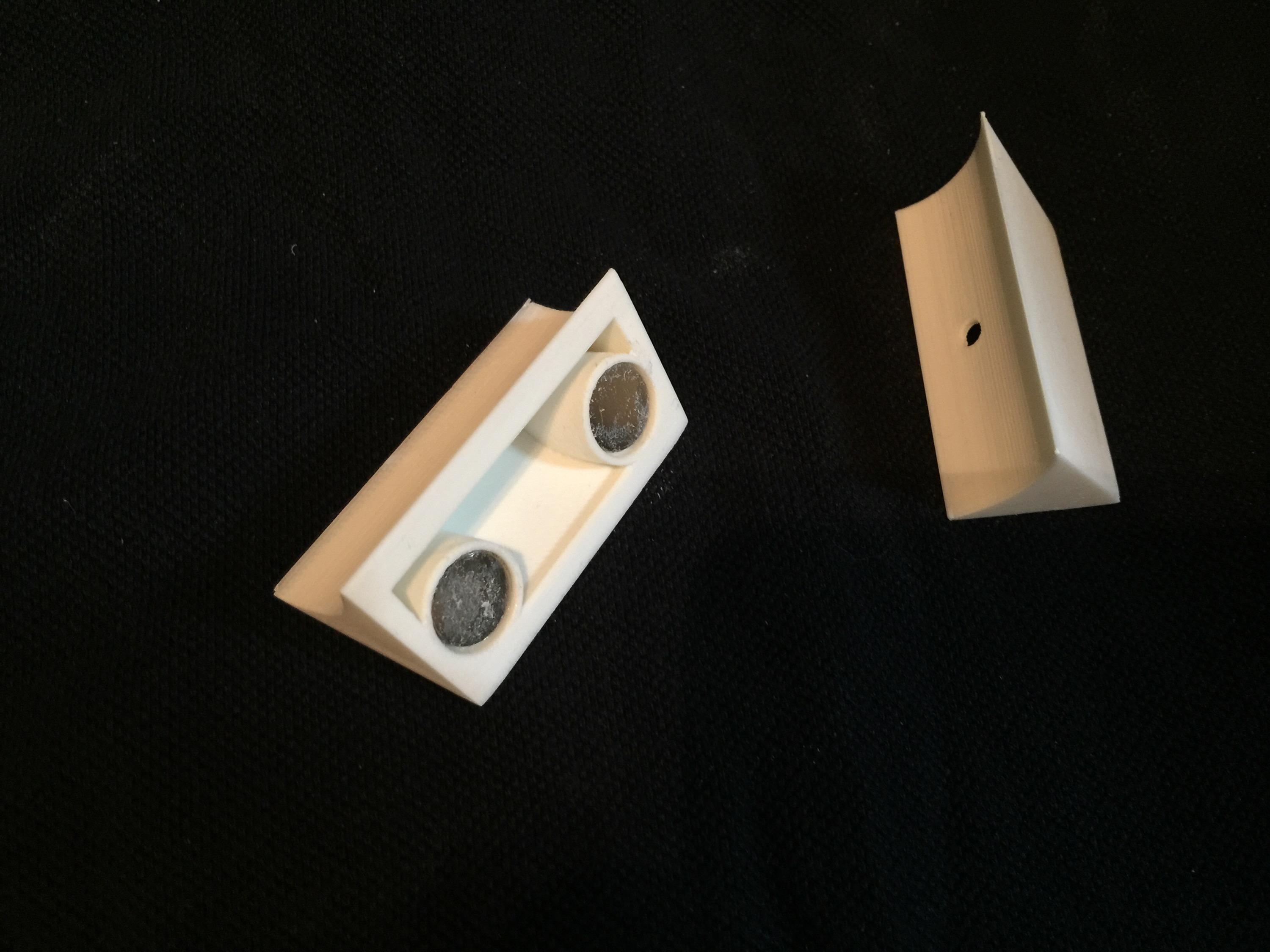
A corner bracket designed, and 3D printed..

After it all came together, it looks pretty nifty!

holodisplay1 holodisplay2 holodisplay3

This will be a nice display at the upcoming Stockholm Comic Con and Sci Fi conventions!


By |2016-12-06T00:00:05+01:00October 2nd, 2015|Building, R2-D2|Comments Off on Vicker Viscount Reading Light Mount

Fixing a cracked ABS print, part 1

The other day, I showed a pic of a print that had cracked quite late in the process.

The reason for ABS prints cracking is due to the temperature issues. Normally you get a lot of warping issues if you have poor print plate adhesion, but I am printing on BuildTak on a heated platform.

I also cheated and used helper disks on the print at the bottom, and I printed near one edge, so once the helper disks were completed, I put clamps around the heated print bed that clamped the helper disks to the bottom, so  even if they would let go, it would prevent the base from warping.

It can, however result in the tension traveling upwards in your print, and that can create a crack. As in my case, a quite sever one that went through 1/3 of my printed piece.

IMG_7936

The best way really to combat cracks and warping, is to put your 3D printer in an enclosure of some kind. My printer, the Makergear M2 that I’ve mentioned earlier in this blog, have a print bed that is moving on the Y-axis. This means that if you want to build an enclosure, it would have to be a rather large enclosure to allow the print bed to travel all the way back and forth.

I simply do not have that space at the moment.

So, I try and do what I can to combat the cracks in my print by tweaking numbers. Making thicker bottom layers to force the plastic into my build surface. Tweaking the extrusion multiplier to get enough plastic to create better layer adhesion. Working with different amount of perimeters on my print, and different types of infill patterns (and settings) to try and reduce these tensions.

I still have not come up with the perfect formula, but I do know that ABS plastic dissolves (quickly) in acetone!

So, I have in the past taken off parts that have shown the possibility of a crack and simply taken a paint brush and painted acetone on the surface. The surface will melt and blend together and create a chemical bond that is as strong as the material itself.

I have also taken filament remnants from an old roll, cut them in small pieces, placed it in a glass jar and added acetone to create a sticky goo that once it cures, it will once again be pure ABS.

THIS .. is my secret weapon for this.

I started by brushing the entire print with acetone. I made sure to get a little extra into that crack. I did not try and force the crack shut, that would only have create more tension in the model.

Instead, once the surface had started to set, I added some ABS goo to the model and tried and push as much inside the mode as I could in the crack, and then used a piece of a break blade knife to spread it out on the surface.

Now, this stuff melts the surface FAST, so there is no real time to do some fancy stuff here, as once it starts to dissolve the surface, you really need to stop working.

I went a little too far, but at the time it was really necessary. This is the result when I left it to cure.

IMG_7937

Tomorrow when it is all cured, I will add another layer of goo into what is left of the crevice and once cured fully, I will sand the ankle, and it should be as strong as ever, and ready for a paint job!

By |2016-12-06T00:00:08+01:00September 2nd, 2015|R2-D2|Comments Off on Fixing a cracked ABS print, part 1

Ankle Work

Since the dawn of time… well.. since R2 was finished originally, that is, he’s had a pair of heavy resin bulks under the Ankle Cylinders.

The Ankle Cylinders was scratch built 3 years ago, and was basically a piece of PVC pipe with thin strips of styrene wrapped around it, with custom made end caps.

See this post for the original build: Scratch building ankle cylinders! They have done the trick up until now, but I wanted to have a set that looked a bit better.

The main reason for revisiting this, is that the original pieces have only been taped to the ankle with double stick tape that has (mostly) done the job, but they have had a tendency to fall off.

I don’t want to glue things in place here, as if I need to do any work on the cables inside, I need to be able to remove these to get to an access hole that is hiding behind them.

I had also lost a few of the ankle wedges (see Building an ankle wedge) that is supposed to sit on top of the cylinders. They were also just taped to the ankle…

The total assembly looked like this: IMG_6906

(Mounting the Ankle… stuff)

But now it was time to fix everything in this area. I had not been 100% happy with the aluminium tape wrapped around the pipe, even if it has done the job.

So, armed with my trusty CAD program, the avid reader know that I have been printing Ankle Cylinders in the past.

This is the parts that I drew and printed:

IMG_7791

These were printed apart to get the grooves in the cylinder as sharp as possible.

IMG_7790

The new ankle cylinders holders. 3D printed, hollow and extremely light. I have glued 12mm magnets inside them for holding them to the ankle later on.

IMG_7789

Here are the new wedges. They are a lot sturdier and better than my old ones! These ones also has magnets inside them. The idea is to pin the wedge inbetween them.

IMG_7792

Like this.

Since I can disassemble these, it makes for easy painting.

IMG_7911

End pieces sanded and ready for painting!

IMG_7909 IMG_7910

I started off by painting them with a filler primer. I chose this as it fills up any imperfections after not sanding enough, or print imperfections.

A dab of the old “Satin White” ..

IMG_7914

… and some R2 Blue…

IMG_7912


… add a little rub and buff …

IMG_7918

… and the assembly should be ready for mounting on the droid.

IMG_7919


I must say I am very happy with the results. The rub and buff really looks like metal!

Next up, fixing the magnets to the droid..

All in all, a great upgrade. Next up is adding the new Ankle Details in aluminium and then weather the new pieces on the ankle.

Finale assembly:

IMG_7923

By |2016-12-06T00:00:10+01:00August 30th, 2015|Building, R2-D2|Comments Off on Ankle Work
Go to Top