Building

Mini update!

My original plan was to do a 40% scale version of my R2.

Well .. This plan has changed. The new plan is to make a 50% scale version of R2-D2.

Why the new format, you may ask? –Well, the slightly larger scale makes the details really pop out from the printer.

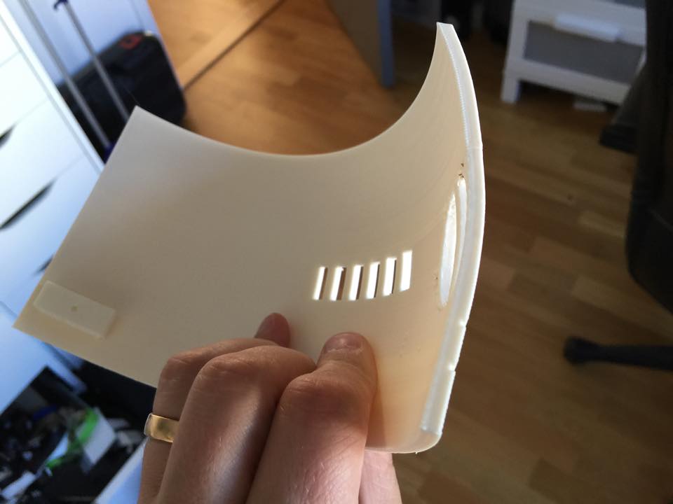
I can’t print the entire dome in one go, but I might as well split it in several parts. The first proper dome print was splitting the dome in half, and printing it in halves. It came out really well.

IMG_7049

It is quite thin at this point, but once ready, the parts really look good.

IMG_7059

It also means I need to print a complete new set of greeblies for the dome, and of course, the old 40% leg struts and parts done, needs to be remade as well.

IMG_7010 IMG_6995

I just think this is so cute.. 😉

The second dome I made much thicker, and split in 4 parts. The main dome is in thirds, but I also cut off the top to print as one single part as well.

Much sturdier…

ThickerDome2 ThickerDome1


However, still fragile..

IMG_7482

Fortunately, this is an easy fix, and once I have acetone coated the insides, it should be sturdy and have no issues at all.


By |2016-12-06T00:00:17+01:00August 24th, 2015|Mini-R2|Comments Off on Mini update!

Disaster, Recocery and moving along…

Last week, I took R2 out to a gaming/cosplay convention in Uppsala, Birdie Expo!

Birdie is also one of very gracious sponsors of the VERY nice R2 Builders backdrop we (now) have!

IMG_3892.JPG

Anyway, day 1 went by well, I managed to get some time in hooking up a servo, rerouting some cables (the quick and dirty version) and doing some code on both my receiver and the new arduino I placed inside R2.

Since I was doing most of this on the fly, with a lot less tools that I usually use, the result was… well .. let’s call it “less than optimal”.

Sure, I got R2 working GREAT with both the new code and the new panel and some of the extra tidbits in it (still not finished with the code, but that will be done at a later time), but .. the results are quite horrible.

The insides of my R2 body now look like this!

IMG_3884.JPG

The extra amp, speakers, arduino and servo, without any properly done cabling at all, has turned my once so tidy R2 inside to a gigantic web!

So what was the results? .. well … this!

So, end user result is great, and I’m really happy. It is also the FIRST motorized servo in R2 I’ve done code for, so it marked a milestone!

For well over a year, I’ve had servos in the dome hooked up with no place to go. Now, this will change..

Second day of the Expo started out great.

I thought I’d get some time doing some tweaks in the control board when times were slow, but after a quick update, something went terribly, TERRIBLY wrong!

R2 started jerking, moving by himself and seemed really weird!

A little debugging told me that the communication between the bluetooth wireless Wii Nunchuck I was using, and my controller board had gone bananas. Instead of receiving real world values, it started receiving random signals.

Turns out that the old libraries used (third party) had not been upgraded in the past 3.5 years, and the later versions of arduino seemed to rupture something. (I did try and reinstall an old version to no avail).

So, I had to sit down and focus and see if I could fix the issue.

It ended up with me programming an arduino library for the nunchuck myself from scratch. I had no idea how or what to do when starting out.

About two hours later, R2 is back and moving again! PHEW!

Good thing though, is that now I can throw out the buggy code, and maybe even get more third party nunchucks working with better resolution!

Back at home after the ordeal, I’ve spent a few evenings looking in to the updated controller code, and will soon move over to the whole new branch of code I’ve written and improved upon from the original R-Series code to various contributions form other people.

Not wanting to sit and just do coding, I decided to get the hooked up servos in the dome moving.

I decided to not use the small Adafruit breakout board for 16 servos that I had, mostly because I cannot detach the servos at will, like I can with normal Arduino coding.

Said and done, I found a Servo shield at a local hobby place, bought it, took it home, only to realize that it was the shield version of the same Adafruit PWM board.

Now, that board could work great, if only I knew how to detach a servo in it, and unfortunately I don’t.

Instead, I purchased an empty shield and did some soldering. An hour or so later it was time to make the cables for it (which is a really fidgety job that takes way longer than people think, cutting, peeling, crimping, removing bad crimps, peeling, crimping again, realize it is not sitting tight, remove the second bad crimp and make a third one… and so on.

Once that was in the head, I started hooking things up and got really weird results from the first servo. First servo alone. It wasn’t supposed to be doing anything… yet.

I removed all code that would make any servo move, and still I got really weird results from a servo. Why? what’s going on?

I pulled everything out again and started writing from scratch… turns out that after a bit of googling on what I found, pins 0 and 1 on the Arduino are earmarked for Serial connection, so you have to disable the serial in order for them to work as a normal pin….

Once I found that out, I managed to get a sketch going, and started setting max and min values on the servos.

Not having a lot of time, I did not have time to investigate why one of the servos are not moving. The pie panel not moving in the video is not moving since the nut and bolt that was holding the piano wire that connects to the servo, fell out. Something to fix later on when I investigate why my servo on the 3rd panel doesn’t work.

Here’s a quick video I took after setting the max and min values. I’m not done yet by a long shot, but at least it is a start!

That’s all for now!

more updates next week!

By |2016-12-06T00:00:18+01:00May 19th, 2015|R2-D2|Comments Off on Disaster, Recocery and moving along…

Side speaker mount done!

Quick update.

I drilled the metal brackets holding the new speakers, coated the inside of the “pockets” where the speakers will reside with black felt..

IMG_3845.JPG

.. and hot glued the perforated aluminium backplates in place.

IMG_3844.JPG

I might need a little more hot glue, but that is a minor issue, as I can always add that later on.

Finally I decided to hot glue the metal brackets in place as well, as I really don’t need to bolt them in to place at this point just yet. It is difficult to drill through inside the body, and the industrial strength hot glue is good enough to hold them in place. If not, I’ll just gently pry them lose and replace the hot glue with E-6000 once I get a new fresh tube.

IMG_3847.JPG

After trying to fasten the missing hatch in the front, I needed to adjust the hinge somewhat, si I snapped it lose (it was only superglued into place after all), tampered with it slightly, and glued it back in place with the last of my E-6000. That should hold it firmly in place!

As a final thing, I had to test it, and naturally, I can get quite a lot of volume out of the droid. I could still do with more bass, so who knows… Maybe it’ll be a low end speaker or subwoofer inside at some point.. make sure everything inside rattles lose 😉

Once the tests were done, I also had to try out the freshly made driving sound. I recoded this over Christmas at work from one of my colleagues electrical re-positionable desk and worked with the sound file late last night.

Now off for an early evening. Last night of building for this time around tomorrow. Who knows, Maybe I’ll get around to switching the drive train to the one I fixed a few weeks ago. I’m still driving around with my old scooter motors, rather than my newer, fancy twin Jaycar direct drive system…

By |2016-12-06T00:00:19+01:00May 12th, 2015|R2-D2|Comments Off on Side speaker mount done!
Go to Top